可膨胀导体有着广泛的应用。然而,制备高效的可膨胀器件的困难在于如何在可膨胀管路上可控构建二维褶皱网络。本文报道了一种通过在预膨胀导管上包裹高取向纳米管阵列(SACNS)所制备的高膨胀性导体。所得的结构有包含一维平行褶皱、交叉褶皱的高效二维褶皱结构,并且所测得可逆形变可以达到7470%的体积变化。二维SAVNS褶皱结构在可逆大形变中拥有良好稳定的导电性和表面润湿性。在可膨胀肿瘤切除的中的体积形变传感器及可膨胀调频天线中基于此结构有着良好的应用。
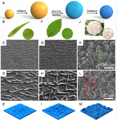
Figure 1. (A) Fabrication steps of a SACNSm/catheter, where the catheter was omnidirectionally inflated. (B, F and J) The photographs of plant leaves for demonstrating the patterns of different types of buckle structures: parallel buckles (B), crisscrossed buckles (F), and hierarchical buckles (J). (C E) SEM images of low (C) and high (D) magnifications of the SACNS5/catheter and schematic demonstration (E) of quasi-parallel buckled structure. The alignment direction of carbon nanotubes is vertical. (G I) SEM images of low (G) and high (H) magnification of SACNS5/catheter and schematic demonstration (I) of crisscrossed buckles prepared from overlap of vertically- and horizontally-aligned carbon nanotubes. The bi-axial omnidirectional fabrication strain was 13% for (C), (D), (G) and (H). (KM) SEM images of low (K) and high (L) magnification and of SACNS5/catheter and schematic demonstration (M) of hierarchically buckled structure. The alignment direction of carbon nanotubes is vertical. The bi-axial omnidirectional fabrication strain was 430% for (K), and (L). The green circles in (K) demonstrated the second order ravines and the red curves in (L) demonstrated the first order buckles.

Figure 2. (A F) SEM images showing the evolution of the buckled structure for a SACNS5/catheter ( fab = 450%) during the biaxial stretch. The strains are 0%, 20%, 50%, 100%, 200%, and 300% for (A) to (F), respectively. (G I) Electrical properties of SACNSm/catheter. (G) Length-normalized resistance as a function of strain for SACNSm/catheters with different m. (H) Percent resistance change as a function of strain for SACNSm/catheter. (I) Length-normalized resistance as a function of m for SACNSm/catheters at different strains and the inset shows percent resistance change for a SACNS5/catheter during inflation/deflation cycles.

Figure 3. Application of SACNSm/catheter on tumor ablation by electro-heating. (A) The dimensional image of SACNS5/catheter and Hepa1-6 tumor in vivo. (B) The optical image (left) and the thermal image (right) of SACNS5/catheter at 3 min during the treatment progress. (C) The thermal image of the tumor 10 min after electro-heating through SACNS5/catheter. (D) The photos of mice and excised tumors during the period of electrical heating treatment. The tumor growth curves (E) and body weight changes (F) of mice in the control and treatment groups (mean ± SD, n = 3).
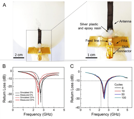
Figure 4. (A) The optical image of the Ag24 nm-SACNS1/catheter monopole antenna with glass epoxy panel with grade of FR-4 and SMA connector attached. (B) Comparison of the measured (solid curves) and simulated (dotted curves) return loss for the Ag24 nm-SACNS1/catheter monopole antenna at 0% and 20% strain. (C) Return loss of the Ag24 nm-SACNS1/catheter monopole antenna for cyclic inflation/deflation tests. The omnidirectional fabrication strain is 80%.
文章链接:https://pubs.acs.org.ccindex.cn/doi/pdf/10.1021/acsami.8b19241